
Charlotte Code-Enforcement Official Installs Buildera CRACKMON® 5020AV Crack Monitors On His Own Home
CRACKMON 5020AV Caliper Crack Monitors Track Foundation Cracks from Expansive Soil
GREG LOWITZ, Buildera

FIGURE 1. Expansion cracks from clayey soil is a likely culprit of veneer cracks.
SUMMARY
When former Charlotte, North Carolina code-enforcement official Gary Josephs noticed vertical cracks propagating through the brick facade of his own home, he tapped a reputable structural engineering firm for forensic advice. Under the firm's recommendation, Gary launched an ongoing crack-monitoring investigation effective September 2015. Over the ensuing 12 months, this Buildera case study will document Gary's use of CRACKMON® 5020AV crack monitors to investigate and analyze crack motion and differential foundation settlement.
BACKGROUND
In 2014, Gary retired from the Mecklenburg County Code-Enforcement Department (Charlotte, NC) as a Mechanical and Plumbing Plans Examiner. He has a Mechanical Engineering Technology degree and holds multiple state and International Code Council (ICC) code-enforcement certifications. His four-bedroom, two-bath ranch-style home—built in 1971 [1]—stands in an established residential neighborhood, 10 miles south of downtown Charlotte. As the second owner, Gary purchased his home in 1985. Over the years, Gary noticed interior wall cracks and sticking closet doors—symptoms of seasonal foundation heaving and settlement. During recent inspections, cracks had propagated through to the exterior brick facade. Determined to find the cause and possible remedies, Gary commenced a forensic investigation to evaluate the foundation stability, and to correlate differential crack movement to weather, soil moisture, and other geotechnical factors.
“The soil is a brown-gray clay, bull tallow, plastic, highly susceptible to moisture, and very expansive”
GEOTECHNICAL CHALLENGES
Mecklenburg County covers a 546 square-mile area surrounding Charlotte, NC and is home to over one million residents, as well as several Fortune 500 companies in banking, energy, and manufacturing [2]. According to recent geotechnical reports, the area falls within the Charlotte Belt of the Piedmont Physiographic Region, principally composed of clayey soils underlain by sandy silts and silty sands on top of parent bedrock, such as granite and gneiss [3].
The homeowner and structural-engineering memo assert the presence of expansive soil that heaves during wet periods and shrinks during dry spells [4]." The soil is a brown-gray clay, bull tallow, plastic, highly susceptible to moisture, and very expansive," notes Gary. Soil-surface desiccation cracks during the dry season are telltale signs of expansive clayey soils. When saturated during the rainy season, the soil swells into a gooey, plastic substrate that exerts extensive pressure on shallow-footing foundations, typical of many residential structures. Resulting foundation damage from expansive clay soils is well documented. Rogers et al. state that "swelling clays derived from residual soil can exert uplift pressures of as much as 5,500 PSF, which can do considerable damage to lightly-loaded wood-frame structures" [5].
The literature is clear that differential soil moisture can cause foundation upheaval globally [6], causing cracks that propagate from the foundation up through the brick veneer and internal drywall. Although such cracks do not indicate imminent structural doom, they can be unsightly and annoying. The annual cycle of patching and repairs is endless. Should a foundation crack, moisture may penetrate to the steel rebar, causing long-term corrosion potential in the footing and potential failure. If left in disrepair, cracks can also lead to water intrusion of inaccessible areas, causing eventual dry rot or mold.
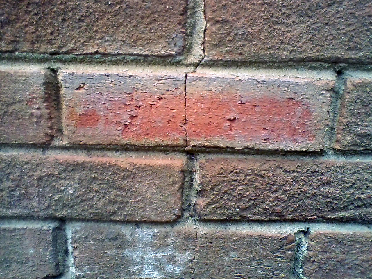
FIGURE 2.
HOME CONSTRUCTION AND CRACKS
Gary's 2,200 square-foot home consists of a traditional shallow perimeter concrete footing with girders set on isolated interior piers. The crawlspace clearance expands from a snake's width at the front, to approximately four feet towards the rear. A drainage ditch 100-feet away from the house consolidates surface runoff. The overall lot slope is good, with no signs of standing water under the home, even during torrential storms (colloquially called frog stranglers).
Mortared brick-veneer circumnavigates the four-bedroom, two-bath home. In the crawlspace, cracks appear at least through the exposed stem walls, and likely extend down through to the footing. No sprinklers are present alongside the foundation, and drought-tolerant plants adjacent to the foundation require no irrigation.
During the dry summer season, a Bermuda high-pressure zone hovers off the Atlantic seaboard, limiting the rainfall, which typically averages 42-44 inches per year. Gary recalls seeing fewer (or smaller) cracks during wetter months, which this forensic investigation will scientifically quantify.
The summer of 2015 was particularly dry with negligible rainfall. Dry soil would promote foundation settlement relative to the saturated condition. The local utility company regulates water levels at nearby dams, but the local water-table depth is unknown to the homeowner. Set 200 meters above sea level, the east wall (worst) includes two vertical cracks stretching 1-1.5 meters (3-5 feet) long, emanating from the foundation, and terminating at a window opening. The worst crack is approximately 5 mm (3/16") at the widest point. The front (north wall) also has a hairline crack concentrated near the corner where the east and north load-bearing walls intersect. There is a fourth crack on the south-facing exterior. This portion consists of an attached slab-on-grade utility room with a water heater. An opening through the brick facade accommodates the dryer vent (utility room). Gary notes that the utility-room siding is Hardiplank®, and that the door leading to the water heater needs occasional adjustment to close properly.
Foundation Design Tips to Mitigate Structural Cracking
To prevent foundation damage, modern engineering practices employ multiple strategies to stabilize the ground moisture and mitigate wild seasonal swings. Methods include:
- Positive surface drainage away from the structure [5]
- Perimeter French drains to keep the foundation moisture more stable during heavy rain [7]
- Deep-pier foundations that extend well below the seasonal moisture zone, thus ensuring consistent skin friction to support the structure in place [8]
When performing engineering calculations, the friction contribution between the surface and the moisture zone, or zone of expansive soils, is ignored since this cannot reliably provide the necessary skin friction at all times of year. Typically the first four to eight feet are ignored, depending on the boring samples. This is aggravated by poor compaction that can occur during grading operations for new sub developments, where loose or newly deposited soil can be several feet deep.
SOLUTION
To assess long-term and cyclic differential crack movement, Gary installed two crack monitors along the east-facing wall, and a third crack monitor near the rear (south-facing) utility closet, which sits on a slab, adjacent to the house. Based on several recommendations from his engineer, Gary ultimately purchased three Buildera CRACKMON® crack monitors and mounting epoxy from Amazon.com.
- The Buildera CRACKMON® 5020AV is a cost-effective crack-monitoring tool that helps engineers track progressive crack displacement on concrete, masonry, steel, and wood-framed structures. An accurate analysis of present structural factors is crucial when carrying out any forensic analysis, which is achievable when trending differential settlement metrics over time.
- Typical crack monitors have a 1-mm visual resolution. The CRACKMON 5020AV crack monitor includes two rigid standoffs to augment visual measurements using a calibrated dial or digital-type calipers. This allows measurement resolution as small as .025 mm (0.001"), limited by the caliper itself.
- Using Buildera STRUPOXY® structural epoxy adhesive, Gary installed three CRACKMON crack monitors over cracks on two sides of his home. Gary checks for changes in crack width at frequent intervals (several times monthly), keeping meticulous notes of changes and environmental conditions.
- To facilitate record keeping, Gary uses the Buildera TRACARD® crack documenting system to document X-Y changes, as well as other forensic metadata such as ambient temperature and subjective soil moisture. When taken as a whole, this information provides powerful forensic evidence of structural changes, including seasonal variations.
INTERIM RESULTS
SEPTEMBER 7, 2015 - ESTABLISH BASELINE CRACK-WIDTH MEASUREMENTS
The first step in crack analytics establishes an initial crack-width baseline. Due to the small, irregular crack patterns, Gary found it awkward to rely on his analog calipers to measure initial crack magnitude. Instead, Gary used the pocket-sized Buildera CRACKMON 224R Crack-Width Comparator to document initial crack widths—ranging between 0.050" (1.3 mm) and 0.140" (3.6 mm) along the crack trajectories.
Mobile-phone photos in Figures 3-5 show the 0 (X)-0 (Y) baseline measurements immediately after installating three Buildera CRACKMON 5020AV Caliper Crack Monitors on Monday September 7, 2015 at 4 PM EDT. The ambient temperature at the time of installation was 86º F (30º C) with a 69% relative humidity (RH%). Note that future differential crack measurements along the X-Y axes will be relative to the baseline reference established on September 7, 2015. The CRACKMON 5020AV Caliper Crack Monitor integrates two caliper standoffs to improve measurement accuracy beyond what is otherwise possible with the naked eye.
- Using the inner jaws of his vintage 6-inch Browne & Sharpe 599-579-2 dial caliper (0.001" resolution), Gary recorded baseline inner-caliper measurements of 4.585, 4.587 and 4.583 inches (≈116.5 mm) for cracks 1-3, respectively
- This measurement does not represent the actual crack width, but rather, the inner distance between the caliper standoffs on the crack monitor itself (assuming a 0-0 starting position)
- Tight clustering affirms excellent measurement consistency between devices of just ±0.002 inches (±0.05 mm), assuming constant temperature
- Slight variations in caliper jaw pressure can account for a few thousandths of an inch of variability between measurements

FIGURE 3. Buildera CRACKMON 5020AV crack monitor installed at position No. 1 between crawlspace vent and window along eastern wall. Initial crack width varies between 0.050 and 0.100 inches (1.27 to 2.54 mm). Inside caliper measurement reference: 4.585 inches.

FIGURE 4. Buildera CRACKMON 5020AV crack monitor installed at position No. 2 between finished grade and third brick course along eastern wall. Initial crack width varies between 0.100 and 0.120 inches (2.54 to 3.05 mm). Inside caliper measurement reference: 4.587 inches.

FIGURE 5. Buildera CRACKMON 5020AV crack monitor installed at position No. 3 on South wall utility room (slab on grade). Initial crack width varies between 0.120 and 0.140 inches (3.05 to 3.56 mm). Inside caliper measurement reference: 4.583 inches.
FIRST RAINS AND ONE-MONTH RESULTS
In the days following initial installation, scattered rain fell between September 9 and 12, 2015 after a dry summer. New caliper measurements on Sunday, September 13, 2015 showed only slight changes of ≈0.002 inches (0.05 mm) from previous measurements. Cracks 1-3 measured 4.587, 4.585, and 4.583 inches, respectively—well within expected manual measurement tolerances. Subsequent periods of precipitation fell between September 24-27, and again from September 29 through October 3, 2015, including brief periods of heavy rain between October 2-3, 2015 [9].
The following interactive Plotly chart shows differential crack-displacement measurements over a one-month period, between September 7 and October 9, 2015. A worst-case peak-to-peak differential change of .0135" (0.34 mm) occurred in Crack 1 (blue line) between September 20 and September 26, 2015. This amount of change is relatively small, and it is too soon to correlate differential movement to rainfall or other geotechnical factors. Of note is that all three cracks closed after the rainfall period in late September, yet this pattern is harder to discern in early October. It's possible that the by the time, the ground was already partly saturated from the earlier rain, effectively reducing the swell potential of the soil.
Impact of Thermal Coefficient of Expansion on Crack-Measurement Readings
Knowing and documenting the temperature at the time of each crack measurement is important to ensuring the highest degree of measurement precision, and provides an opportunity to post-correct for measurement errors due to temperature differentials. All materials experience differential expansion and contraction versus temperature, albeit to different extents [10]. Over typical outdoor temperatures ranges, the coefficient of thermal expansion of most synthetic materials is approximately constant. This means that the change in length of a specimen is approximately linear (proportional) with the change in temperature.
Ambient (air) temperature serves as a proxy for slow-changing temperatures, and may be used as a baseline when material temperature is impractical to measure. Where ambient temperatures change quickly, it can vary widely from the substrate temperature in materials such as brick and concrete, which have high thermal mass. Thus, the material temperature will often be out of phase (lagging) with respect to the ambient temperature, based on the material's ability to absorb, retain, and release heat. Ideally, measuring core substrate temperature provides the most accurate results.
METHODS TO REDUCE CRACK-MEASUREMENT ERRORS DUE TO TEMPERATURE CHANGES
To mitigate or reduce the error contribution of material expansion and contraction due to temperature differentials between sequential measurements, Buildera recommends taking crack measurements at or near the same temperature every time. Thus, in this example, with the first set of measurements taken at 86º F (30º C), subsequent measurements on different days should also repeat at or near 86º F (30º C). However, as fall and winter approach in the Charlotte area, average daily temperatures naturally decrease—with average temperatures in January of just 39ºF (4ºC), and minimums dropping below freezing. This represents an average differential temperature of Δ-47ºF (Δ-26ºC) from the initial baseline measurement at 86ºF (30ºC) degrees. Clearly, it is not always practical to take measurements at a constant temperature. In such cases, Buildera suggests keeping the temperature differential to as small as practical. Methods to achieve this include a local understanding of monthly temperature profiles, and attempting to make measurements at a time of day that keeps the measurement temperature within a tighter annual range of ±10ºF (±6ºC) of target.
To better quantify how this temperature differential affects crack-measurement accuracy, one must consider the materials and compare their differences. In this case study, two disparate materials dominate the core errors due to thermal expansion:
- Brick (fired-clay measurement substrate)
- Crack monitor (thermoplastic measurement device)
According to Ross [11], testing of 139 clay-brick samples of various origins reveal a distribution of expansion coefficients with an arithmetic mean of 6.1 ppm (parts per million) per degree C over a material temperature range of -10 to +40ºC (14º to 104ºF). By contrast, the coefficient of thermal expansion of concrete is slightly higher at 7-14 ppm per degree C. This variation depends on the type and ratio of materials, size and amount of reinforcement, as well as humidity and other factors. Accounting for thermal expansion of masonry (and concrete) is essential to avoid thermal-expansion cracks in the first place [12]. Many cosmetic cracks are associated with insufficient expansion joints or flexible sealants, and may have little or nothing to do with the soil.
Over the length of a typical 8" brick, an average measurement temperature differential of 26º C between summer and winter may cause material expansion or contraction of approximately 8"*26*6.1, or 1,269 ppm, or .0013" (0.033 mm). Depending on assumptions used for the anchor endpoint restraint, this example assumes that the brick is secured at one end, and expands freely towards or away from the crack. Thus, this expansion rate effectively doubles when factoring in relative motion of both sides of the brick, on either side of the crack.
One could argue that such small changes are negligible, and are within the typical measurement accuracy range and repeatability of a dial or digital calipers. Thus, for practical purposes, over the length of an 8" brick, this amount is small relative to the measurement resolution, and can be safely be ignored. If the whole wall were to shift, relative to an anchor point (such as a corner), then the total expansion could be much greater (proportional to the wall length between expansion joints and the crack). In practice, the entire wall behavior is difficult to model without a controlled environment in which to run tests.
The crack monitoring devices in this case study—CRACKMON 5020AV—each consist of two opposing and overlapping plates. The bottom plate includes an X-Y measurement grid, and the top plate includes a red crosshairs that serves as a reference point relative to the underlying grid. Each plate is approximately 110 mm long, and is manufactured from polycarbonate—a high-performance polymer that resists impact.
Most thermoplastics have thermal expansion coefficients that are five-to-ten times higher than materials such as concrete and clay brick. For example, the CRACKMON 5020AV has a specified expansion coefficient of 68 ppm/ºC over -40 to +80ºC. Assuming that any thermal expansion occurs from the edge of the secured (epoxied) mounting flange to the far extent of the measurement grid, this length measures approximately 80 mm. Thus, in this example, over a 26ºC temperature variation between summer and winter, each length of the crack monitor could expand by 68 ppm * 26* 80 mm = 0.141 mm (0.006"). Factoring both sides of the crack monitor, the effectivly doubles worst-case thermal expansion errors of 0.282 mm, or .011". At crack widths around the center point of the crack monitor, the thermal expansion will be less since the unrestrained length from the point of measurement is proportionally reduced. That said, the measurement error introduced purely by thermal expansion is on the order of 0.012 to 0.025 mm (.005 to .010"), which is well below what the human eye can detect using solely the measurement grid to read measurements. Note that the specification for visual measurements is ±1 mm resolution with ±0.5 mm visual accuracy (interpolated).
To help minimize errors and improve measurement precision, the CRACKMON 5020AV also includes a caliper standoff on each plate. The location of the standoff is adjacent to the mounting area, thus temperature changes will have a negligible impact on the reading since the measurements will take place near the anchor points of the end of each crack monitor plate. That said, it's notable that the measurements in the chart above are within this range. In all likelihood, some portion of the change in observed crack widths is due to thermal expansion changes of the substrate, the crack monitor, as well as true changes from expansive soil, precipitation, and other structural or geotechnical factors.
Monitoring IMPROVEMENTS
As this case study progresses, Gary and Buildera are collaborating to improve data accuracy and relevancy. For example, a Fluke 62 MAX IR Thermometer now measures the surface temperature at the time of measurement. This will provide more accurate temperature-related data. In addition, a soil moisture meter is also being deployed to measure relative soil moisture at the time of each measurement. Over time, a better understanding of the surface temperature and soil moisture will help to provide better insights into the causes of crack movement.
Interim Summary
This case study will continue for approximately 12 months, through at least September 2016. This allows ample time to record changes in Cracks 1-3, across four seasons, including periods of wet and dry weather. Results from the first month of observation are indeterminate due to limited data collection. Thus far, measured crack-width changes in the range of .005 - .010" (0.12 - 0.25 mm) can be expected due to thermal expansion of the substrate and crack monitor, which is well below the visual discrimination range of the crack monitor itself. Detecting and recording such minute changes are only possible using a crack monitor with integrated caliper standoffs, such as the Buildera CRACKMON 5020AV and similar.
ACKNOWLEDGMENTS
The author is grateful to Gary Josephs for his cooperation and contributions to this case study, including photographs.
REFERENCES
- Zillow.com. Web. Accessed 03, 2015
- Wikipedia. Web. Accessed 03 Sep 2015
- "City of Charlotte Streetcar Starter Project Report of Geotechnical Investigation," June 2012 FINAL. Terracon Consultants, Inc. (Charlotte, NC). PDF. Web. Accessed 07 Sep 2015
- M.P. Gervais, P.E.. Engineering Memo to Gary Josephs, September 17, 2012. Intelligent Design Engineering, Charlotte, NC
- J.D. Rogers, R. Olshansky, and R.B. Rogers. "Damage to Foundations From Expansive Soils," Missouri University of Science and Technology. PDF. Web. Accessed 03 Sep 2015
- K. Venkataramana. "Building on Expansive Clays with Special Reference to Trinidad," West Indian Journal of Engineering, Vol 25 No. 2, 2013. PDF. Web. Accessed 04 Sep 2015
- R.H. Lanoie and G.E. Lowitz. "Principles of Drainage and Basement Waterproofing," Builders Websource® Tech Note 051000-1, 2012. Web. Accessed 07 Sep 2015
- "Various Aspects of Expansive Soils Relevant to Geoengineering Practice," Missouri University of Science and Technology, GE 441, Spring 2004. PDF. Accessed 03 Sep 2015
- Forecast.io Time Machine. Web. Accessed 29 Oct 2015
- "Crack Monitor FAQs: Frequently Asked Questions About Crack Monitoring," Buildera. Web. Accessed 29 Oct 2015
- C.W. Ross. "Thermal Expansion of Clay Building Bricks," Journal of Research of the Nation Bureau of Standards, Vol 27, August 1941, U.S. Department of Commerce. PDF. Web. Accessed 13 Sep 2015
- "Accommodating Expansion of Brickwork," Technical Note 18A, Brick Industry Association, Nov 2006. PDF. Web. Accessed 13 Sep 2015
CREDITS
Application story by Greg Lowitz.
Photos ©2015 Gary Josephs, reproduced with permission.
©2015 Buildera. All rights reserved. Please contact Buildera for written authorization to reproduce electronically or in print.